Retaining walls are widely used in landscape architecture to strengthen areas located on slopes, steep slopes, ravines, and hills. Retaining walls prevent landslides and landslides in areas with sharp elevation changes, so their design and construction is of great importance. The materials from which retaining walls are constructed are very diverse: natural stone, reinforced monolithic concrete, concrete blocks, wood, gabions, metal mesh, decorative concrete, etc. Structures for strengthening slopes can vary in design, height, and also , for its intended purpose.
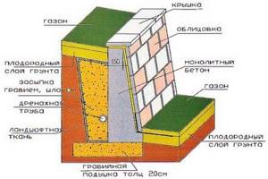
The design of any retaining wall invariably includes such basic elements as the foundation, wall body, drainage and drainage.
Construction of a retaining wall
When all the parameters have been calculated and the configuration and dimensions of the wall have been selected, you can begin its construction
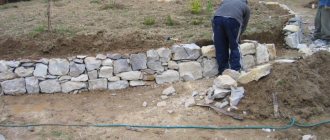
Trench
This is the first stage of construction of the supporting structure. Markings are applied to the land plot in accordance with the given shape and thickness of the future structure, taking into account the width of the foundation, and a trench is dug.
![]()
Construction of a trench for a supporting structure
The bottom of the trench is thoroughly compacted with a shovel. The side cuts are given an even geometric shape. A gravel or crushed stone cushion is laid at the bottom of the trench.
![]()
Gravel bed at the bottom of the trench
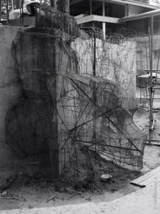
To enhance the strength of the foundation, reinforcing mesh or metal rods are laid on top of the gravel. Reinforcing bars are installed along the contour of the trench in a vertical position to ensure the strength of the structure.
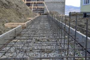
Support wall reinforcement
Formwork
Formwork
Retaining walls made of monolithic reinforced concrete require the construction of a massive formwork structure that can withstand the pressure of heavy concrete mortar.
- Formwork panels are made from boards with a thickness of 3 cm.
- They must be connected horizontally to each other using vertically installed beams with a cross section of 5 x 10 cm.
- The structure is fixed using spacers installed in the ground every 50 cm on both sides of the structure.
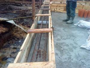
- First, install the rear wall of the formwork.
- To avoid deformation and deflection of the frame, vertical metal reinforcement is installed along the wall. At this stage, a drainage system is installed.
Retaining wall drainage
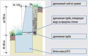
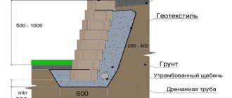
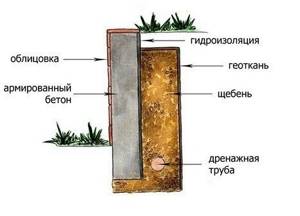
Retaining wall in section
Drainage may differ in location:
- Transverse drainage
Transverse drainage
A hole with a diameter of up to 10 cm should be left in the body of the wall, or a tube with a diameter of 5 cm should be inserted at an angle in increments of 1 m. The drainage is carried out into a nearby water intake.
Cross drain pipe
- Longitudinal drainage
Longitudinal drainage
A corrugated drainage pipe is laid at the level of the foundation, wrapped in geotextile material, which absorbs moisture and allows it to enter the holes of the pipe, from which it is discharged outside the structure.
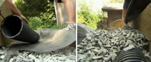
Laying a longitudinal drainage pipe with your own hands
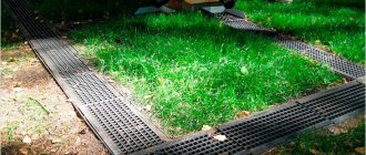
Each of these options involves laying a drainage layer between the wall surface and the soil. The drainage layer can consist of gravel, broken bricks or coarse sand 7–10 cm thick.
Important! The drainage layer is installed at the stage of soil filling. Instead of fractional materials, you can use a modern drainage fabric made of bulk textiles, then additional pressure on the supporting wall will be eliminated.
Solution
In order for the retaining wall to withstand high loads and be durable, it is necessary to use high-quality frost-resistant concrete mortar. For monolithic thin-walled reinforced concrete structures this is a solution of grade B10/B15, for prefabricated structures - B15/B30.
Frost resistance of concrete:
| Temperature, °C | Minimum frost resistance class |
| from -5 to -20 | F50 |
| from -20 to -40 | F75 |
| from – 40 and below | F150 |
5 days after the solution has set, the formwork is removed. The outer surface of the structure is treated with cement plaster. In a month, the concrete will gain its working strength and will be able to bear the load.
At this stage, the space located on the rear side of the structure is filled. In order for the solution to be of high quality, the instructions for its preparation and the required proportions must be followed.
Calculation and installation of retaining walls
The architect, when starting to design a retaining wall structure, proceeds from building codes and regulations (SNiP); studies the climatic conditions of the area, the hydrological regime, and takes into account possible loads on the future structure. For these studies, soil analysis is carried out in field or laboratory conditions, and the height of the wall is calculated according to the vertical planning project of the territory.
To ensure that the retaining wall does not deform and begin to collapse due to loss of stability, a detailed calculation of the stability of the structure is required during design. All horizontal and vertical loads on the wall are taken into account. In order to avoid major deformations of the reinforcing walls, such as the wall collapsing onto the ground, shifting or overturning, the designer plans a slope towards the backfill at the rear edge of the wall, and also arranges drainage in the backfill. To reduce the active soil pressure and increase the passive pressure, the back face of the retaining wall is made more rough. Also, in order to prevent tipping over, a console ledge is attached to the front side.
Calculation of bearing capacity in the design of retaining walls includes: a) calculation of the stability of the structure against shear and the strength of the soil foundation, and b) calculation of the strength of all wall elements and their connections.
Filling the space behind the supporting structure
First, fill the drainage soil or lay the drainage fabric, which was mentioned above. After this, the previously selected soil mass is laid in layers of 20–40 cm, which must be compacted as it is backfilled. The top layer is plant soil.
![]()
Filling the back wall space
After a few weeks, natural shrinkage of the soil will occur, so it will be necessary to backfill.
Important! You cannot add previously removed peat, silt, soil in which the content of organic and soluble inclusions exceeds 5% by weight, as well as frozen soil.
Stages of construction of retaining walls
The technology of construction and design of retaining walls made of geosynthetic shells includes several stages:
1. Soil is prepared and supplied from places near the construction site to fill geosynthetic shells of certain sizes, which open on one side to receive and store the soil. Geogrid, main mesh and seeds for landscaping are also prepared.
2. A base layer of soil is formed on which the retaining wall will be built by leveling the work area.
3. The prepared geosynthetic shells are filled through the open side with a pre-measured amount of sand and local soil in a ratio of 80% to 20% [8]. After binding the open side, the geosynthetic shell is placed in a molding machine and vibrated to form a parallelepiped that has greater strength.
4. The first level of the retaining wall is formed by continuously placing multiple shells in a horizontal position. Fixing elements are driven through the top side of the shells to the base ground level, firmly securing the shells.
5. In a similar way, the second layer of the retaining wall is installed with an offset relative to the shells of the first layer. The second level is secured by driving in the fixing elements to the mid-height of the shells of the first level.
6. The retaining wall is built to the required height by performing the fifth stage repeatedly. The end of the geogrid, placed at a certain interval, is firmly fixed in the geosynthetic shell with the help of a fixing element, and its other end is horizontally extended to the back side of the retaining wall and recessed when backfilling the soil, thereby supporting the structure.
7. One end of each of the two geogrids is placed on the upper sides of the shells at regular intervals formed in the fifth and sixth stages and secured with fixing elements. The other end of one of the geogrids is facing the front side of the retaining wall, the last one is facing the back side, and in this state, the geogrid facing the front side surrounds the geoshells located in the upper part and is covered by the geogrid extended in the direction of the back side of the retaining wall. Thus, the top shells are installed in a double structure, one end of which is pressed when filling the top layer of the retaining wall with soil.
8. A mesh woven from palm or hemp fiber is installed over the entire surface of the retaining wall. The cross-section of a geosynthetic shell retaining wall is shown in Fig. 1.
9. Planting material is made by mixing seeds, soil and humectants in a certain ratio and cast at a certain thickness using a pumping device to form a green carpet on the surface of the retaining wall over time.
The fixing element on the designed retaining wall is made of:
- a rod whose underside is conical so that it can easily penetrate geosynthetic shells;
- a plurality of teeth formed integrally on both lower sides of the rod and designed to prevent separation of the rod from the shell;
- T-shaped fixing part on the upper side of the rod;
- conical projections on both lower sides of the T-shaped part of the rod.
The fixing element is made of synthetic resin or high-strength metal. In addition, the locking element may be of a different shape, for example, in the form of a plate with a number of conical protrusions connecting two or more shells, or it may be absent altogether.
In Russia, geosynthetic shells are used in the construction and design of retaining walls in a vertical position without fixing elements; filling is carried out by bunkering devices, excavators or dredgers and barges. Geomatrices are also used - rectangular multi-sectional structures sewn from a series of geosynthetic shells.
Waterproofing the surface of retaining walls
Waterproofing a retaining wall
The rear wall of the retaining structure must be reliably waterproofed using roofing felt or roofing waterproofing material (roofing felt). They are laid in two layers on bitumen mastic. If the soil is dry, then it is enough to treat the back surface of the support with two layers of bitumen.
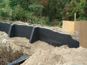
Treatment of retaining wall with bitumen
Types of Retaining Wall Designs
Based on the massiveness of the constructive solution, retaining walls can be divided into 2 types: thin-walled and massive. The wall's own weight and, to a greater extent, the weight of the soil involved in the work of the wall structure provide stability to thin-walled structures. They are made from materials such as architectural concrete, reinforced concrete. Massive retaining walls, mainly, are given resistance to shear and overturning by their own weight under horizontal soil pressure. Materials from which such walls are made: decorative reinforced concrete, brick, rubble stone.
Design of retaining walls. Part two.