Drilling methods
Before finding out the answer to the question of how a well is constructed, it is quite logical to study the methods and devices that contribute to its formation. Possible drilling options:
- Diamond drilling. Named after the type of working tool. It is used extremely rarely due to its high cost.
- Turbine drilling. Water wells are created through the use of a turbo drill. When the turbine rotates, it makes translational movements. The process uses drill pipes.
- Electric drill. Operation of the device requires its preliminary connection to an energy source. The drilling process is easily controlled from the surface.
- Hydrodynamic drilling. Its use is relevant for creating filterless structures. Indispensable in cases where it is important to strictly adhere to the form.
- Auger drilling destroys the rock, which is then lifted up. Used when working with soft rocks for shallow wells. This technique is very popular, but is completely unsuitable for working with hard areas.
- Pneumatic hammer drilling. Relevant for use at shallow depths. It has high energy consumption, so it is rarely used by dacha owners.
- Screw engines. Working with them is reminiscent of turbine drilling. The relatively small dimensions of the screw make its operation more comfortable. Often used to create water intake systems in summer cottages.
The main stages of drilling in the following video:
BC 1xBet has released an application, now you can officially click on the active link for free and without any registration.
Drilling an Abyssinian water well and creating a well
Well operation principle
The operating principle is identical for all types of water intake wells. What is it?
- After drilling the well, the casing pipe is installed. It can be steel or plastic, perforated or asbestos-cement. Such a device protects the walls from crumbling, as a result of which the water becomes polluted and the source ceases to function over time.
- The primary purification of liquid from solid particles is performed by a filter. It is fixed to the bottom of the casing. To do this, burn or drill holes. The perforated part of the device is covered with a filter mesh.
- A cap is used to seal the mouth
- The pump lifts water through the pipes. It is installed after the installation of the casing.
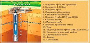
Important! A check valve, cable and pressure pipe are first connected to the pump. The power of the equipment is calculated based on data - the distance of the well from the consumer; the distance between the aquifer and the ground.
- The water riser pipe is connected to the water supply pipe.
- Insulate the well.
- All necessary elements for water supply automation are installed, including a pressure control system.
Well design
A borehole is a long, narrow opening in rock, also called a shaft. Drilling involves lowering a drilling tool into a shaft on a rod made of pipes or on a rope.
A pipe is lowered into the trunk - casing, which will ensure the integrity of the walls of the trunk and prevent them from collapsing under rock pressure. The casing sits tightly in the barrel or with the annulus. It is filled with clay or concrete.
The lower end of the trunk is plugged, open or with a slight narrowing - a bottom. The upper part of the trunk is the tip. A well is being installed around it.
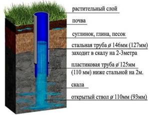
Well design
Functional components of the well
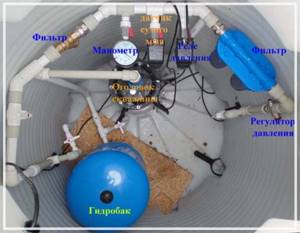
The well has quite a lot of elements:
- Water intake. Its design is characterized by the presence of a mesh and a check valve.
- Suction line. Through it, water enters the pump housing or pumping station.
- Directly the pump. It sucks in liquid and lifts it up under pressure.
- Pressure switch.
- Hydraulic accumulator. Protects against water hammer.
- Electric motor.
Downhole pumping units and automation
To extract water from wells, surface and submersible electric pumps of a centrifugal operating principle are mainly used. The advantage of this design is the ability to create high pressure in the line, thanks to the use of units with a large number of impellers, which allows increasing the pressure in each subsequent stage.
Household submersible electric pumps can lift water from very great depths (about 200 meters), while surface types are used in sources with a water surface at a depth of up to 9 meters from the surface of the earth. To increase the intake depth of surface models, built-in or submersible ejectors are sometimes used, although their efficiency decreases significantly.
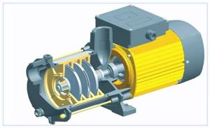
Rice. 11 Centrifugal electric pump
Hydraulic accumulator, relay and pressure gauge
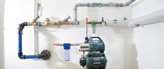
To automate the operation of water intake pumping equipment, an automation system for a well or a pumping station is used, consisting of the following devices:
- Hydraulic accumulator. It is a voluminous metal tank with a rubber bulb inside, which fills with water when the electric pump is turned on. The device allows you to avoid water hammer in the system and optimizes the operation of the electric pump, reducing the number of its on and off cycles.
- Relay. The main element of the automatic control system is a pressure switch, which is connected to the line using a fitting. When pressure appears in the system above its settings, the built-in membrane inside the relay housing through a mechanical system interrupts the supply voltage to the electric pump and it turns off. After consuming water, when the pressure in the system drops, the relay closes the contacts and turns on the electric pump.
- Pressure gauge. The device is one of the main elements in any plumbing system; it allows you to control pressure and configure equipment.
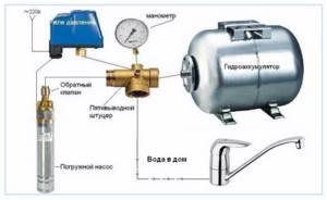
Rice. 12 Automation in the electric pump control system
The design of water wells is not very complicated; the main internal elements that are installed during drilling are casing pipes and a filter in the bottomhole area. To collect water after installing a well, additional equipment and engineering systems (caisson, head, adapter) are used, which make it possible to effectively connect the electric pump to the source, taking into account its location and type.
This is interesting: Moisture-resistant laminate: consider together
Equipment for well construction
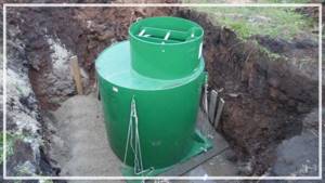
To get the well working, you need to use the following elements:
- Pump with safety rope and electrical cable for subsequent connection.
- An automatic device that will regulate voltage and protect the engine from overheating.
- Hydropneumotank. Its task is to protect against water hammer, regulate pressure, and reduce the frequency of turning the pump on and off. Tank sizes vary from 10 to 10,000 liters. The optimal volume for an average home is 100 liters.
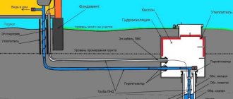
- Caisson. The steel tank serves to protect the equipment needed to lift the water. Installed at a depth of 0.5-1 m.
Attention! The structure must be insulated and waterproofed.
- Wire (which ensures uninterrupted supply) and water pipes (lead from the caisson to the house).
Sequence of connecting elements
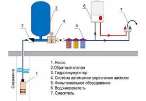
The water well connection diagram has the following order:
Scheme of water supply to a private house from a well
- Externally, the arrangement of the water supply system begins with determining the indicators: the depth of the source and the power of the pump. Most pump units have a built-in check valve, otherwise one will need to be installed.
Important! The check valve keeps the water under pressure.
- Connecting the pipeline should not cause any difficulties. They are installed after connecting the casing pipes with the head and coupling. It is imperative to ensure that the joints are tight, otherwise the pipe may break during operation. The diameter of water pipes must exceed 3.2 cm.
- A ditch is dug between the well and the house. The pipes are laid at a depth of 0.5-1 m and insulated with mineral wool.
- Having decided to supply water using overhead communications, you must also take care of their insulation. Sometimes a heating electric cable is laid for this purpose.
- At the end of the external work, a hole of about 5 cm is punched in the foundation of the building. A sleeve is inserted into it and pipes are inserted. The area is sealed with polyurethane foam.
You can watch the installation of a water well in the video:
Basic methods and equipment for well construction
To extract water from wells, submersible and external electric pumps and pumping stations are used; surface pumping equipment can be located near the wellhead or at some distance from it. To connect electric pumps to a well source, various methods and equipment are used, designed for different types of electric pumps.
Heading
If it is necessary to resolve the issue of attaching a submersible electric pump and protecting the borehole channel from the penetration of dirt and sediment, a cap is used, which is installed on top of the casing pipe. The device is designed for a standard diameter, can be made of plastic, steel or cast iron, and can withstand the weight of suspended pumping equipment up to 250 kg. in plastic version and up to 500 kg. when using metal. The typical design includes a carabiner for hanging the electric pump and an outlet through which the pressure pipe passes when connected to the line.
Structurally, the head is made of two parts, which are connected after the electric pump is immersed in the well. To do this, a flange is put on the casing pipe, pressing it to the surface of the earth, a rubber ring is installed and a second flange with a suspended electric pump is placed on top, fixing it motionless with bolts.

Rice. 7 Heads
Adapter
The adapter allows you to connect a surface centrifugal electric pump or pumping station to a well through a pipeline if they are located at some distance. The pipes are located underground, which prevents them from freezing in winter. The second advantage of this connection is the increase in the depth of immersion of the pressure pipeline into the well by lowering it below ground level, which in surface pumps does not exceed 9 meters.
The adapter is made in the form of two parts, one of which with a connected pressure pipeline is located in the borehole channel, and the second with a water main connected to it is located outside. Both parts are connected through the walls of the casing using threads and an insulating rubber gasket.

Rice. 8 Adapter - structural device
Caisson pit
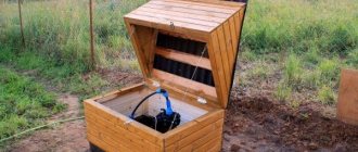
A caisson pit is used in cases where an electric pump and pumping equipment to automate its operation are located near the wellhead. Usually the pit is made in the form of a concrete ring deepened into the ground; sometimes plastic or welded metal structures covered with bitumen waterproofing are used. To prevent groundwater from penetrating into the bottom hole along the well shaft, the bottom of the hole is covered with a cement-sand screed.
Typically, a pumping station or automatic control of a deep-well electric pump is placed in caisson wells: a hydraulic accumulator, a pressure and idle speed switch, a pressure gauge. In addition to insulation from groundwater, the caisson provides protection from freezing not only at the wellhead, but also at the entire water main, which, when used, is located underground.
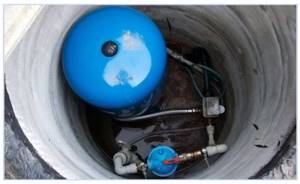
Rice. 10 Caisson well
Well design diagram
Well construction can have various variations.
The design depends on the materials of manufacture and the type of well. In general, the device diagram looks like this:
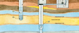
- Water rises from the aquifer, passes through the filter and ends up inside a working with a circular cross-section.
- The turned on pump directs the liquid through the water pipe.
- The water moves upward and enters the receiver, and from there into the water supply.
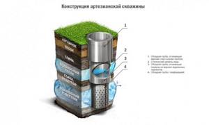
The design of an artesian well is clearly reflected in the photo:
Sand well
A well created on sand is fed with water from aquiferous lenses. Drilling can be carried out both to sand and to gravel layers. It is not always possible to drill such a structure. It happens that there is too little water in the discovered lens and further drilling is impractical. During work, the auger may hit a hard boulder. This will also prevent further work from being carried out.
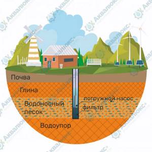
The water in sand wells is in loose soil; when pumping it out, a special filter is required. You can get to the aquifer in 2-3 days, even by hand. If you have special equipment, the speed of work increases, and the well can be ready in 1 day. To prevent the walls of the structure from crumbling and polluting the water, perforated casing pipes are installed throughout its entire depth. Most often their diameter is 125 mm.
Water is drawn through a mesh filter. The size of its cells depends on the type of soil. It retains silt, small stones, and sand. Without a filter, mechanical particles can enter the water supply system and damage it. To extend the operating period, pebbles are placed at the bottom, which acts as an additional filter. To pump water, a special submersible pump is required. It is selected taking into account the productivity of the well and the need for water. Pumping equipment is installed inside the casing.
The depth of the structure on sand reaches 50 m. The pump in it is usually installed at a height of 10-30 m from the bottom. Subsequently, stainless steel pipes are laid from it. The deeper the aquifer is, the purer the water.
The operating principle of this type of water well is as follows. Water from the aquifer penetrates into the well through a filter. After turning on the submersible pump, it begins to pump moisture through the water pipe. It is fed upward into the receiver and moves through the external water supply. Next, through the pumping station, the water passes into the internal pipeline.
With proper operation, such a well can last about 15 years. The longevity of the service is indeed directly proportional to the frequency of use. Only regular pumping of water can prevent siltation of the installation. Another way to extend the life of such a well is to timely clean and replace the filter.

