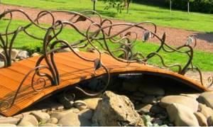
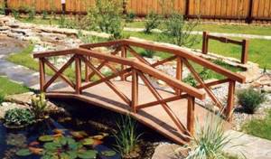
A small pedestrian bridge in the landscape design of a site is a good decoration for a private area, but it can carry more than just decorative functions. If necessary, you can build a bridge for a summer house with good functional load, which will be actively used in an area with gardening activities. In addition, this structure can be decorated with various plants and flowers.
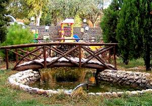
Decorative bridge made of logs in the garden
If you plan and design a bridge for a summer cottage or an artificial home-made pond correctly, it can become a unique place on your site that will attract attention. Before proceeding with the planning of the structure of this structure, it is necessary to understand that ordinary pedestrian bridge buildings for a river on private territory are various structures whose function is to overcome obstacles of various kinds.
There is an opinion that installing a summer cottage bridge is justified for large garden plots. But in fact, they will look good in modest areas. For example, a decorative bridge can be made as a continuation of the garden path at the dacha, which will help overcome an inconvenient place for a pedestrian, and in addition will help make the garden more interesting and intriguing.
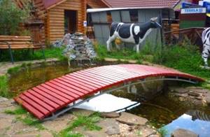
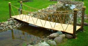
An example of a country bridge made of boards and a metal frame
In order for the decorative bridge in the design to look organic and at the same time luxurious, it is worth planning in advance the design of this structure, suitable for the general type of the site and the river.
If you have a small area at your disposal, then you need to choose the simplest possible bridge design, and its color should be neutral, not particularly noticeable from the color scheme of the entire territory. The next thing you need to pay attention to when planning a decorative bridge is the selection of a suitable design and its location.
Basically, such structures are a good addition to a garden and a house that has a river on the territory, so components and building materials must be selected just to match the style of the rest of the territory.
It is also worth considering the presence of various buildings, such as a pallet shed, a wooden gazebo or lanterns, which will be located next to it.
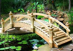
Construction of a wooden bridge over a pond in the garden
If your garden plot is located in an area with differences in ground height, especially if there are low-lying areas that are filled with water in the spring, having a forged bridge is a necessity. Another situation in which a bridge is a good addition is the design of a road leading to a wooden gazebo. By making such a special structure near the recreation area, the owner will be able to give his summer cottage a look of completeness.
There are several basic requirements that must be observed when installing a forged bridge:
- Harmony with the design of the garden and house, as well as the beauty of the design of the path laid out to it, thanks to which this structure will be interesting and bright.
- High functionality of this structure. The bridge should not only be a good decoration, but also a strong support that can withstand a weight of at least 300 kilograms.
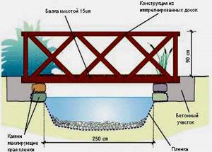
Diagram of the construction of a simple bridge for a summer residence.
In addition, attention should be paid to the angle at which the rise in the bridge should be made. If it is strongly curved, then it will become uncomfortable to climb, and it will be perceived more like an obstacle. - High reliability and safety structure. Thus, the bridge in the garden should be durable and easy to cross. During its construction, it is necessary to take care of a good coating, which should not be slippery during rain or winter.
DIY decorative bridge
The main task of those who want to build a garden bridge with their own hands in their summer cottage is to choose the type of structure, as well as the correct selection of landscape design. One of the options for designing a bridge for a private area is monolithic buildings. The second option is to use natural and available materials, such as smooth natural stone, plank squares or circles.
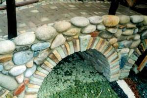
Option for a decorative bridge made of natural stones
One of the most exotic and at the same time beautiful options for large ponds is to lay out the entire structure from stones. This option will help to achieve a combination with an already laid path from scrap materials on the coastline, decorated in the same style.
It is worth noting that for such a decorative bridge, it is necessary to select stones of the same size and type. One of the main conditions for the construction of such a crossing is the depth of the reservoir, which should be no more than 45 centimeters. The minimum height to which the bridge must rise above the river is 10 centimeters.
To make the surface on which the crossing will be as comfortable as possible, its width should be at least 60 centimeters. Another option for decorating a small garden bridge with your own hands from natural material is to use non-standard stones.
Such material will be especially relevant if it has a smooth and comfortable upper part. Such a structure is well suited for areas where flowing waters create small wave fluctuations at the site of a natural obstacle.
Today, there are a large number of different concrete imitations that replicate the shapes of natural boulders. Concrete material has a high level of strength, and it is also well protected from the negative effects of high humidity.
If the owner of a site with a river wants to create a cozy corner on his territory with the help of a connecting bridge, then he must follow the following tips:
- It is necessary to make a foundation for the entire structure. To do this, you will need to empty the reservoir of water. Next we move on to laying the stones. It is necessary to ensure that the surface of such a structure is strictly horizontal.
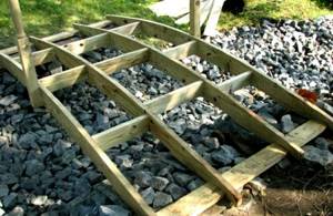
Installation of a wooden bridge frame - Now you can proceed to installing iron or brick pillars. For this you will need ordinary bricks. By installing these building materials perpendicularly, you will get a support protruding above the river for a short period.
- The third step is to install the decorative surface. For this purpose, flat stones measuring 60 cm or more are used, which are firmly fixed to the brick supports using mortar.
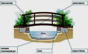
Diagram with dimensions for installing a bridge across a river on the site - After completing all work, you must wait at least 3 days, which will make the structure on the site more stable. Only after this can water be released into the updated area.
DIY wooden bridge construction
To make a decorative garden bridge from boards and blocks of wood, it is not at all necessary to buy new materials. In some cases, improvised means are also suitable. Before you begin building connecting bridges for the pond, you need to make sure you have the right tools. The tips below will help you install a bridge for a small area with your own hands.
If there is liquid in the reservoir, it must be drained. After draining the bottom of the water obstacle, you can proceed to installing pre-prepared boulders. Each of the bars should be laid on a good layer of mortar.
An example of a mounted suspension bridge across a stream on the site
After their installation, height leveling is carried out, which is done using previously installed slabs. You should also ensure that the tops of all stones are strictly horizontal. After completing all the procedures, the structure should be allowed to dry for 1 - 2 days.
You also need to think about the path leading to the future building. One of the positive features of a bridge on a summer cottage is the ability to connect two different types of paths that differ in texture. In addition, this structure will help decorate any stream or pond.
In some cases, it is considered inappropriate to create water barriers on your site. But this is not an obstacle to the construction of a small decorative wooden bridge, which significantly increases the attractiveness of the garden area.
For example, the presence of an ordinary stone gazebo in the recreation area of a summer cottage is already a reason for the construction of a bridge, which will serve as both a decoration and a guide for visitors.
Wooden bridges
Details Category:
WOODEN BRIDGES
, bridges, the main material of which is wood.
Currently, wooden bridges are built from pine, larch, and spruce. Oak is used primarily for pillows, dowels, and sometimes for piles and purlins. Forest material d.b. winter felling, erect, with a small number of branches, without circular and radial cracks (frost, metic, frost), without blue and rot. The so-called ore pine
, that is, grown on dry sandy hills.
In wooden bridges under an ordinary road, the width of the driving surface: on field country roads - from 3 m; for driving cattle 4.5-6.5 m; on highways 4.7–6.4 m; on important roads and in cities up to 12 m or more. The flooring, which forms the driving surface, is laid on the crossbars; the latter - on beams or so-called. purlins, single or composite. The distance between the purlins depends on the purpose of the bridge, its design (in connection with this) and the dimensions of the material. The purlins are supported by supports made of piles or posts. Bridges of solid construction use double decking. The top row of flooring boards is intended to protect the bottom row from abrasion. The thickness of the boards of the top row is 5-7 cm, the bottom 8-10 cm. The boards of the top row are laid either along the bridge, or across, or at an angle (in a Christmas tree). When placing the boards along the bridge, a smoother, but more slippery surface is obtained; this method deserves preference when passenger traffic predominates; When heavy freight traffic prevails, it is better to lay deck boards across the bridge. The bottom row of deck boards is sometimes made from plates laid across the bridge and replaces the cross members.
Instead of a device for riding on a boardwalk, you can use crushed stone bark on a single deck made of plates or knurling.
The simplest type of bridge for an ordinary road is a beam bridge, consisting of supports and spans that span the spans (spaces between supports) of the bridge. Each support consists of a number of piles connected at the top by a cap (horizontal log), for which spikes are cut on the heads of the piles, and nests are hollowed out in the cap. Purlins, cross members and flooring are laid along the nozzles, as indicated above. In the simplest cases, the transverse plank flooring is attached from the sides with pressure bars or so-called pavilins
, usually used to install
railings
. When the height of the bridge or the depth of the water is significant, the supports are installed less frequently, i.e., with larger spans.
Significant spans may also be caused by shipping requirements. In these cases, a braced (Fig. 1) system, or a truss (Fig. 2), or a combined (Fig. 3) system is used.
The best angle of inclination of the struts in these systems is 40-45°, from which, due to local conditions, it is sometimes necessary to deviate greatly. To support the joints of the purlins, so-called sub-beams
.
In a truss system, the beam under the purlin, against which the upper ends of the struts rest, is called a crossbar
and is made about 0.4 times the distance between the supports.
The rows of piles in the support are connected by horizontal (longitudinal and transverse) and diagonal contractions made of plates, beams or boards (Fig. 4).
The arched system (Fig. 5) allows you to cover spans of up to 20-25 m or more.
In wooden bridges under the railway, the rails are laid on cross members. The flooring consists of two boards laid between the rails, and 4-5 boards on one or both sides of the track. In case of a train derailment, safety bars
.
For small spans, beam and strut systems are suitable. The truss system for railway bridges is less applicable due to the significant deformations possible in this system under large live loads. The beam system
has spans of 2-4, less often up to 6 m. In this case, in accordance with the pressure on the pile support, one or two rows of piles are placed. If the height of the railway embankment exceeds 8 m, the rows of piles in the support are moved apart from the axis by 1.5-2 m and connected with cross-shaped contractions and ties (Fig. 6).
This measure aims to increase the longitudinal rigidity of the structure. Longitudinal contractions have the same purpose. In the part of the bridge that extends into the embankment, the spans are connected by horizontal braces and struts, which creates a kind of abutment. In the transverse direction, the required rigidity of the support is achieved by driving braced piles, placing struts and contractions (Fig. 7).
For each rail, from 1 to 6 beams or logs are assigned to the run. In a strut system
The struts form one or more intermediate supports for the purlins, which makes it possible, with the same number and dimensions of beams in the purlins, to increase the distance between the supports. An example of a bridge with a braced system is shown in Fig. 8.
An important element of wooden bridges of the bracing system is the tightening
, i.e., a horizontal beam, or log, or plate connecting adjacent supports at the level of the lower ends of the struts.
The purpose of the tightening is to absorb the horizontal component of the pressure of the struts, the so-called. spread
_
Here, of course, it is necessary to have a sufficient number of notches through which the horizontal component of the pressure of the struts is transmitted to the tie, and the vertical component to the piles. If the soil does not allow driving piles, use support supports
or
supports on beds
.
The choice of timber bridge system (beam, strut, truss, arch) depends primarily on the height of the railway embankment, water depth, navigation requirements, ice drift and other local conditions. According to the rules approved by the NKPS, the values of the smallest navigable spans for wooden bridges are as follows: on rivers with little navigation (4th category) - 25 m, on rivers with rafting in bulk and in rafts (5th category) - 15 m, on rivers with rafting only in bulk (6th category) - 6 m. For low railway embankments, beam bridges are appropriate. From a technical point of view, the beam system, as the simplest and having the smallest number of deep cuts, is the best and most durable.
To cover large spans (from 20 to 40 m or more) trusses
.
Trusses are made of beams, logs or boards. There are systems in which all the main parts are made of wood, and systems with metal strands. The last group includes the Gau system, and the first group includes trusses made from boards of the Town and Lembke system. Gau truss
bridges for railways can be, depending on local conditions, with a ride on top and a ride on the bottom. In bridges with a ride on top, the bridge deck is laid on trusses from above. With a small distance between the trusses (2-2.5 m), frequently located under-rail crossbars can rest directly on the trusses. If the distance between the trusses is large, use heavy and sparsely placed transverse beams on the trusses, which support longitudinal beams, laid at a distance of about 2 m from each other and serving as the basis for the under-rail crossbars. In bridges with a ride below, the presence of heavy transverse and longitudinal beams is mandatory. In fig. Figure 9 shows Gau Farm with a ride on top.
The truss consists of upper and lower chords, straight and reverse crossing braces and vertical iron strands. The places where the braces are attached to the chords are called nodes
;
distance between nodes - panel
. The upper belt works in compression, while the lower belt works in tension; ascending braces, counting from the ends of the truss to its middle, are the main ones and are subject to compression, reverse braces at the ends of the truss serve to support the main compressed braces against buckling; in the middle, when a train passes, first one system of braces works, then another, depending on the position of the load. For ease of crossing, the braces in one direction are made double, and in the other - single; connecting the braces - using pads made of oak or cast iron, end-to-end.
The joints of the belts are covered with metal strips with dowels, secured with bolts. Between the trusses, upper and lower ones are placed in horizontal planes, and in vertical planes - transverse links made up of intersecting diagonals and iron bolt ties. As the span increases, Gau trusses take on a more complex form: the number of brace systems increases. At Towne Farms
both the belts and the braces are made of boards (Fig. 10).
Braces work in tension and compression; belts - as usual: upper - for compression, lower - for tension. The braces are attached with dowels and bolts. The thickness of the boards is 5-7 cm, width 25-30 cm. The dowels are oak cylinders, 3-6 cm in diameter. Holes are drilled in the boards with a diameter slightly less than the diameter of the dowel. Between the trusses there are, as indicated above, transverse and longitudinal connections. The load is transferred to the trusses by longitudinal and transverse beams or cross members laid on the upper chords. Lembke Farms
(Fig. 11) are similar in design to Towne trusses.
The difference is that in Lembke trusses the brace boards are placed close to each other. The result is a truss with a solid wall. The wall of the trusses, in order to avoid bulging of the braces, is crimped with vertical, and if its height is more than 2 m, also with horizontal bars. The disadvantage of Towne trusses and especially Lembke trusses is the rapid rotting of the boards. Recently, trusses have been used for wooden bridges, in which the parts are connected using metal Tuchscherer
. Trusses of this kind, in the form of a beam reinforced with a truss system of boards, were used, among other things, by the German concession “Mologoles” for spans of 20 m.
The number of trusses in railway bridges with a ride on top is 2 or 3, depending on the span; with driving at the bottom - 2. The distance between the outer trusses is determined from the condition of the stability of the span against overturning by the wind and for sufficient lateral rigidity of the span it must be at least 1/12 of the span. Rollover safety factor ≥1.40. In bridges under an ordinary road with a ride on top, the number of trusses and the distance between them depend on the width of the deck, on the spanning capacity of the transverse beams and on economic considerations. The most common distances are 2-2.5 m. In bridges with a ride below, the distance between the trusses is determined by the size and width of the passage. The large distance between the axes of the trusses requires particularly strong transverse beams. Trussed beams are used. The height of the trusses is set from 1/4.5 to 1/9 of the span length and must be consistent with the angle of inclination of the braces of 45-50°.
The weight of spans with Gau trusses, designed for decapods (a steam locomotive with an axle pressure of 16 tons, a total weight of 16 × 5 + 10 tons), is given in Table. 1.

The weight of spans with Town trusses under the same load is given in table. 2. Riding - on top.

The weight of spans with Lembke trusses, designed for a normal train of 1907 (20 tons per locomotive axle), is given in Table. 3.

The supports of wooden bridges with trusses are made of piles, frames, cord or stone. In the latter case, a wooden span structure is laid temporarily instead of a metal or reinforced concrete one. A pile support consists of several rows of piles. To provide stability, side struts and grips are used. The row is a box with vertical walls and a through floor. All the walls of the ridge are formed by crowns of horizontally laid logs, fastened at the corners with notches; the upper and lower beds of these logs are hewn to achieve greater density of the seams. The walls of the box are connected by horizontal struts, forming, as it were, vertical through partitions. To strengthen the walls of the row, racks are installed. The ryazh is filled with stone.
To protect the supports from the action of ice drift, ice cutters
. An ice cutter consists of a log (rib) placed obliquely on piles and two planes converging to the rib at an angle. The planes are formed by boards or beams supported by a system of racks, struts and piles. The rib slope is from 1:1 to 1:2. This type of ice cutter is called a tent ice cutter. With weak ice drift and thin bulls, ice cutters have a simpler design: one row of piles with an inclined edge (flat ice cutters), or pile bushes (palas).
Calculation of long-term railway wooden bridges, according to the “Technical conditions for the design and construction of railway wooden bridges”, is carried out for the heaviest composition that can handle on a given line during the period of expected operation of the bridge, but in any case for a load not lower than the O-1925 scheme in relation to the locomotive and tender schemes and not less than 7 tons per linear meter in relation to the car load. To calculate temporary wooden bridges for a period of not more than 3 years, the heaviest composition that will actually move across the bridge is accepted. The wind pressure is considered to be 250 kg/m2 in the absence of a train and 150 kg/m2 in the presence of a train on the bridge. Wooden bridges for an ordinary road are designed for a load specifically established for these bridges. The permissible stresses for wooden bridges are given in table. 4.

Permissible stresses for iron parts in wooden bridges: a) tensile stress in bolts, single ties and linings - 900 kg/cm2, b) tensile stress in ties with 2, 3 and 4 ties working together - 750 kg/cm2, c ) for tension of tie rods with turnbuckles - 600 kg/cm2, d) for shearing of rivets and bolts 0.8 × 900 = 720 kg/cm2. When calculating for the simultaneous action of vertical load and wind, the permissible stresses increase by 15%. For temporary structures - increase by 20%.
The compressed parts are checked for stability, and the reduction factor for the permissible stress is calculated using the formula:
for values l/i > 5 and < 100, and according to the formula:
for values l/i > 100.
In these formulas: l is the length of the rod, i is the radius of gyration, E is the modulus of elasticity of the tree (E = 110,000 kg/cm2 for pine and oak), kd is the permissible stress for simple compression, s = 5 is the safety factor. Free length of compressed braces in Gau trusses = μ l, where
I0 is the moment of inertia of the main compression brace, I1 is the moment of inertia of the reverse brace. Purlins are calculated either as free-lying beams or as continuous beams. When calculating composite beams with dowels, the strength reduction factor is assumed to be 0.70 for two beams and 0.5 for three. The pressure on the supports is determined on the assumption that the purlins are cut at the supports. When calculating complex trusses with several intersections of braces, it is possible to decompose them into simple systems, dividing the load by the number of systems. Piles as racks must be checked for longitudinal bending. The greatest permissible failure (e) in cm is determined by the formula:
where n is the number of blows in the deposit, which is 20 for a manual pile driver, 10 for a machine and steam pile driver, F is the cross-sectional area of the pile in cm2, Q is the weight of the pile in kg, P is the design load on the pile in kg, H is the height lifting of the pile in cm and q - weight of the pile in kg (with a headstock, if one is used).
The service life of wooden bridges is 8-15 years. To protect against rotting, tarring with hot wood resin, impregnation with various compositions, or painting are used.
The approximate cost of wooden bridges is indicated in the table. 5 and 6.

The cost of bridges for an ordinary road: small holes is 9-20 rubles. per m2 of canvas, large holes (200-300 m) - 25-50 rubles. per m2 of canvas (at prices before 1914).
Source: Martens. Technical encyclopedia. Volume 6 - 1929
- < Back
- Forward >
Designing a bridge for a dacha area
The main condition for arranging bridge structures in a dacha area is the material from which the structure is made. For this purpose, the same construction and finishing elements are selected that were used when laying out paths, installing gazebos or other interior elements.
Since one of the cheapest, but at the same time beautiful materials for the construction of a decorative bridge is wood, it is worth thinking about increasing the service life of wooden elements. To do this, you can use the simultaneous use of wood and metal materials.
Project and drawing with dimensions of a metal bridge over a stream
The metal parts of the bridge will be in most contact with water, which will significantly extend the life of the structure. One of the most popular stone options for designing a bridge structure is granite or sandstone. This option is especially relevant for areas where masonry or stone compositions were actively used.
If the area where it is planned to build a forged bridge is small or has a small body of water, then the construction of a large bridge, which will take a lot of time and resources, is not justified. In such cases, it is best to use a large slab of sandstone, which can be laid on each of the banks of the stream, thereby connecting them. If it is not possible to use large materials, forged bridges are perfect.
DIY decorative bridge
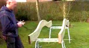
Do you think building a bridge is a very difficult task? It is not at all necessary to use complex iron structures or bend around solid parts.
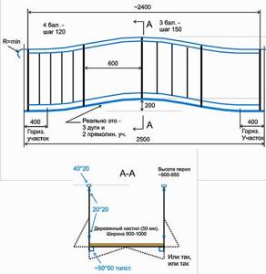
A classic humpback structure can be installed in just one day, if you take into account the following nuances:
- Very thick boards are chosen for the base of the bridge. You can also use a wooden beam.
- For a small pond, two integrated beams with a cross section of 50 by 200 millimeters and 2.4 meters in length are suitable.
- The most difficult thing in such a project is to draw a straight line along which the wooden material will then be sawn.
To begin with, measure 120 millimeters from the length of the beam, leave a mark on one edge of the board, then find and mark the middle of the beam. At the other end of the material we measure 40 centimeters. We carry out similar work with the second beam.
Now we connect the mark in the middle of the board with the drawn mark on the sides of the wood. In this way, auxiliary lines will be obtained. Each of them has a center, and a measurement is placed halfway between the extreme and middle marks. This task requires some skill. If the worker is not confident in the success of the marking of the structure, it is best to make a template from paper.
When drawing a curve, you must remember that the distance between the edge of the beam and the top of the arc is only a couple of centimeters.
Having completed the drawing, we will get a pattern on the beams, which will subsequently need to be cut out. To do this you will need a special saw with a narrow blade. A jigsaw will also help with this task. Its advantage is that it is quite easy to turn. Having finished processing the wooden material, we place the resulting curved part on top of the remaining boards.
Design of a summer cottage bridge made of wood
Thanks to this, you can see how part of the taken material has taken the form of a part necessary for the construction of this structure. Now the resulting parts need to be connected. To do this, you can use four bolts with a diameter of 10 millimeters and a length of 220 mm.
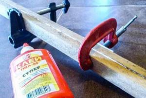
You need to draw a mark where the bolts will be located. It is best to place the same fastening material at a distance of up to 10 millimeters from each other. Using two clamps we fix the parts of the future bridge. In order to make the necessary holes, you can use a large drill bit.
It must be remembered that when making a hole on the curved side, the drill must be held at a slight angle, which will greatly facilitate the further fastening of all elements of the bridge. To securely fasten two bases for a wooden bridge, you must follow a certain procedure:
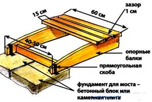
Diagram for assembling a wooden bridge
- drill the upper part completely, and only half drill the lower part;
- remove the top part;
- drill the bottom part to the end (this will now be much easier to do, since the direction has been set in advance);
- install the upper part in its original place, after which it is necessary to mark with a simple pencil the points of contact between the upper and lower parts;
- to secure the structure, apply PVA glue between these marks;
- fold all parts of the bridge base and fasten them with clamps;
- at the end, bolts are placed on pre-drilled holes and secured with washers.
The second part for the base of the garden bridge is made in the same way. The finished parts can be used as a template for the second part. By applying the curves of the finished stringer to the board, you will get two identical parts. After manufacturing the second part, it will be possible to begin mounting and decorating the entire structure.
The two base elements must be connected to each other by thread. The drilled holes should be located 5 cm from the bottom edge and 10 cm from the sides. To save time, the two bridge base pieces can be drilled simultaneously with an 8mm drill bit, stacking the bridge pieces on top of each other.
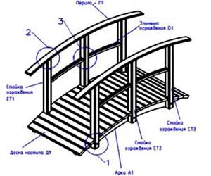
Design drawing of a country bridge
On one part of the base we screw the threaded pin and secure it with a nut and washer on both sides. Now you need to measure how much distance is needed to secure the second part of the base on the other side of the pin. Thanks to this structure, the width of the structure can be easily adjusted and the distance between the foundations of this building can be changed.
After pre-fixing the fasteners, you can begin assembling the bridge. Before finally tightening the washers and nuts, it is best to double-check the width of the sides of the building. Afterwards, you need to tighten all the nuts as much as possible and check the width of the bridge again.
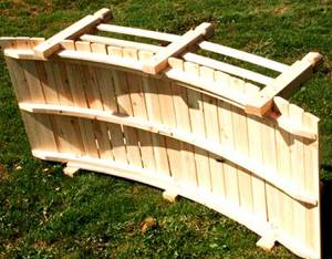
Final bridge assembly before installation
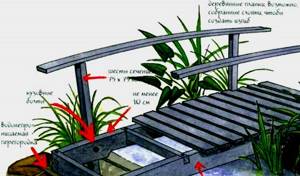
The protruding parts of the rods can be cut off using a hacksaw. Now we begin to stuff the cross boards onto the bridge. They should protrude slightly beyond the edges of the base. It is best to use self-tapping screws to attach the planks.
In order to select the appropriate fastening material, it is necessary to take all measurements in advance and, based on the data obtained, buy self-tapping screws. But before you start attaching the boards, it is best to mark out places along the entire length of the base for installing the planks. The best distance between two boards on which people will walk is one centimeter.
Construction of spans
Installation of prefabricated reinforced concrete spans
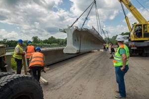
Superstructure beams
Installation of ribbed span structure
Design of prefabricated beam spans
Prefabricated beam spans can be divided into ribbed and slab. Span structures are formed from individual mounting blocks - beams or slabs.
The most widespread in recent years are ribbed span structures (SS) made of entirely transportable T-beams with a total length of up to 33 m with monolithic longitudinal joints along the beam slabs.
Manufacturing of fully transportable beams and their transportation
The production of prestressed fully transportable beams with reinforcement tensioned on stops before concreting at MRC plants is carried out using flow-aggregate technology in specialized workshops
Features of manufacturing standard T-beams with frame reinforcement
Currently, frame beams are often manufactured using the bench method at the bases of bridge construction organizations engaged in the construction and repair of bridges. Metal drop-down formwork is used to form the beams.
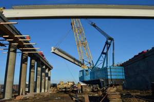
Cranes used to install beams
In bridge construction, general construction and special cranes are used for bridge construction. General construction cranes are preferable to special ones due to the scarcity of the latter and the need for their transportation, assembly and disassembly, which increases the time and cost of installation.
Schemes and rules for slinging beams
When loading and unloading beams and their installation, it is necessary to strictly follow the rules for slinging (grabbing) beams. For slinging beams with hooks and slings with a length of up to 15 m, loops are provided in their designs.
Varieties of technological installation schemes
To select optimal schemes for the construction of floodplain and river-bed spans, variants of technological schemes are developed and compared according to technical and economic indicators.
Integrated assembly of split composite reinforced concrete beams
With a beam length of 42 m and a weight of 90 t, the beams enlarged in this way are installed in the design position using a sluice crane with a lifting capacity of 100 tons or two gantry cranes.
Installation of prefabricated continuous spans
Continuous spans made of ribbed beams were widely used in bridges and overpasses. The design was based on the use of standard prestressed beams with a length of 33 and 24 m.
Installation of reinforced concrete prestressed composite spans
Design of prefabricated beam-continuous prestressed spans
Superstructures with spans of up to 150 m are assembled from individual blocks up to 4 m long and weighing up to 60 tons. The blocks are manufactured at MZhBK factories or landfills. Length-composite reinforced concrete spans have been successfully used for both beam and frame systems.
Installation of reinforced concrete prestressed spans
For the construction of continuous beam span structures, the following installation methods are used:
| Stage No. | Work order |
| 1 | Assembly on solid scaffolding |
| 2 | Hinged balanced and semi-hinged assembly of continuous spans |
| 3 | Span-by-span assembly on longitudinally movable steel scaffolds of slab-ribbed spans (PRS) |
| 4 | Assembly with a cantilever-sluice crane unit |
| 5 | Slide in combination with conveyor-rear assembly |
| 6 | Enlarged assembly on shore with subsequent installation of the span into the design position by floating means |
Construction of monolithic beam prestressed spans
Design of beam spans
Monolithic beam prestressed span structures can be continuous, including curved in plan, while the number of expansion joints is significantly reduced, which is important for the normal operation of structures.
Process flow options
| Stage No. | Work order |
| 1 | Cyclic longitudinal slider |
| 2 | Span-by-span concreting. Most widely used in Western Europe |
| 3 | Concreting a solid span on a solid scaffold |
| 4 | Suspended concreting using cantilever-type units |
| 5 | Overhead concreting using a sluice-type unit |
Concreting of beam continuous prestressed spans on solid scaffolds
Currently, concreting spans in sections on solid scaffolds is widely used. The length of sections, as a rule, includes 2-3 spans.
Overhead concreting
Superstructures concreted using the suspended method usually have a box-shaped cross-section with vertical walls, with a constant or variable height along the length
Cyclic longitudinal slider
The essence of the method of cyclic longitudinal sliding or, more precisely, conveyor-rear concreting with longitudinal sliding is that sections of a span of 20 or more meters in length are concreted on a slipway, and after tensioning the reinforcement, the structure is pushed into the span
Construction of steel-concrete beam spans
Design of steel-reinforced concrete spans
The construction of steel-reinforced concrete spans abroad began in the late 1940s. Steel-reinforced concrete bridges of different systems are used: beam, frame, combined. Steel-reinforced concrete stiffening beams are used in cable-stayed and suspension bridges of small spans.
Installation of standard steel-concrete spans with precast reinforced concrete slab
The construction of steel-reinforced concrete spans is carried out in two stages. On the first, steel structures are installed in the design position, on the second, a reinforced concrete slab is mounted.
Basic schemes for installing steel beam structures in the design position
| Stage No. | Work order |
| 1 | Longitudinal sliding on permanent supports with foreback |
| 2 | Longitudinal sliding on permanent and temporary supports |
| 3 | Longitudinal sliding along permanent supports using a truss |
| 4 | Longitudinal slide with floating support |
| 5 | Longitudinal sliding from two banks along permanent supports with closure in the middle of the main span |
| 6 | Mounted and semi-mounted assembly |
Construction of steel-reinforced concrete spans with a monolithic slab
When concreting a slab, it is necessary to strive to eliminate as much as possible the harmful effect on the longitudinal profile of the deflections of steel beams from the weight of the concrete being placed. To do this, the slab is concreted in several stages and temporary supports are installed in the middle of the spans
Installation of beam continuous box-shaped steel spans with an orthotropic roadway slab
Design of box spans
Box spans with an orthotropic roadway slab are much lighter than steel-reinforced concrete ones. At the same time, they have sufficient torsional rigidity and also have significant technological advantages
Conveyor-rear assembly with cyclic longitudinal slider with foreback
Longitudinal sliding with a front back is most often used for bridges and overpasses with a box-shaped orthotropic structure. The assembly of the span is carried out on the approach embankment, on a special slipway, which is located along the axis of the bridged span.
Installation of steel spans of a through system
Design of through spans
For spans up to 84 m, it is possible to arrange a classic roadway design with a beam cage of transverse and longitudinal beams and a reinforced concrete roadway slab. For large spans, it is advisable to lighten the roadway by using an orthotropic roadway slab
Assembly of through spans of a split system with flexible belts on solid scaffolds
The assembly of spans on solid scaffolds differs from other methods in the simplicity and safety of the work, as well as high accuracy.
Semi-mounted assembly of beam through spans
During the semi-mounted assembly of spans, the scaffolding is not constructed as a solid structure, but in the form of separate supports (frames) located under the truss units with flexible belts
Mounted assembly of through-span structures
The suspended installation of a metal span structure using the hinged assembly method is based on the principle of gradually building up the span between permanent supports without scaffolding or temporary intermediate supports.
Longitudinal sliding of through spans
The general scheme of work organization is similar to that used for solid-wall span structures. First, the span is erected on the shore using a floor-by-floor, sectional or combined method. Then its longitudinal sliding is carried out.
Installation of through spans on supports using floating equipment
The installation of through spans using floating means is used quite often on large rivers for multi-span bridges in the presence of a fleet of pontoons or barges.
Construction of arch, suspension and cable-stayed bridges
Construction of arched bridges
Monolithic arches are concreted for spans of up to 20...30 m without dividing into sections with intensive laying of the mixture in layers on both sides from the heels to the castle. In addition to concreting on scaffolds and circles, it is possible to use the method of suspended concreting and mounted assembly.
Construction of cable-stayed bridges
Basic assembly diagrams for cable-stayed spans with steel stiffening beams:
| Stage No. | Work order |
| 1 | Suspended assembly with a minimum number of temporary supports |
| 2 | Longitudinal sliding of stiffening beams with fore-beam and truss |
| 3 | Assembly on temporary supports |
Construction of suspension bridges
| Stage No. | Stages of work |
| 1 | construction of anchor (shore) supports; |
| 2 | construction of foundations for pylons and installation of pylons; |
| 3 | installation of temporary hanging scaffolds for installation work on the construction of a support cable from parallel wires; |
| 4 | installation of stiffening beams and suspensions |
Construction of the bridge deck
The bridge deck is the most loaded element of the bridge during operation. It is under the influence of force and natural factors (dynamic effects of transport, rainwater and snow, deicing agents, loads from mechanisms used in the operation of bridges and roads, temperature effects, etc.).