In any country house or private building located within the city limits, the owners have at their disposal household appliances and power equipment, the use of which can lead to emergency situations. They usually manifest themselves in the fact that in some equipment the insulation is damaged, after which the supply voltage phase hits the metal case. If one of the residents accidentally touches it, he receives a strong electric shock, which can lead to irreparable consequences. To avoid such situations, protective grounding is organized in any modern building, designed to reduce the dangerous potential affecting a person during emergency operation of the equipment.
Is grounding necessary in a private house?
Reliable grounding in a private home is necessary, if only because the requirements of the PUE do not allow the operation of household appliances in it without protection from dangerous voltages.
Please note: In addition, unlike city apartments, in country houses a 4- or 5-core cable with a three-phase power supply of 380 Volts is allowed.
Such an input allows you to install a small milling machine on the site, for example, as well as connect asynchronous motors and other types of power equipment to the power supply line.
Grounding of all metal components in a private house
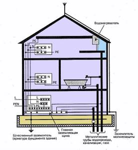
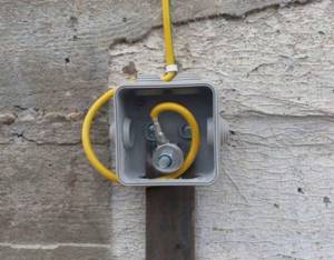
If it is planned to equip a swimming pool or sauna in a private country house (that is, objects associated with high humidity), the issue of a potential equalization system will definitely need to be considered. Its organization will make it possible to combine all large metal components of a given facility (including steel pipelines and metal doors) into a single chain. And that, in turn, is connected to a ready-made ground loop, as shown in the photo on the right.
Grounding principle
To make it clearer why grounding is needed in houses or in the country, we need to consider the principle of its operation, based on the fact that electric current always chooses the shortest distance for drainage. In other words, electronic carriers always flow into circuits that have minimal resistance. In an emergency situation, when the current-conducting body of the device becomes energized due to insulation damage, this is precisely what happens. If this has already happened, the only thing that can protect the user working with them is the presence of a chain to drain dangerous current.
Its branching can be achieved by installing a special grounding circuit (GC), the individual elements of which are connected to the housing of the protected electrical equipment. Thanks to this, the emergency current that poses a threat to humans is reduced to a safe value. The latter is explained by the fact that most of it flows into the ground along a parallel chain formed by the ZK design (see photo below).
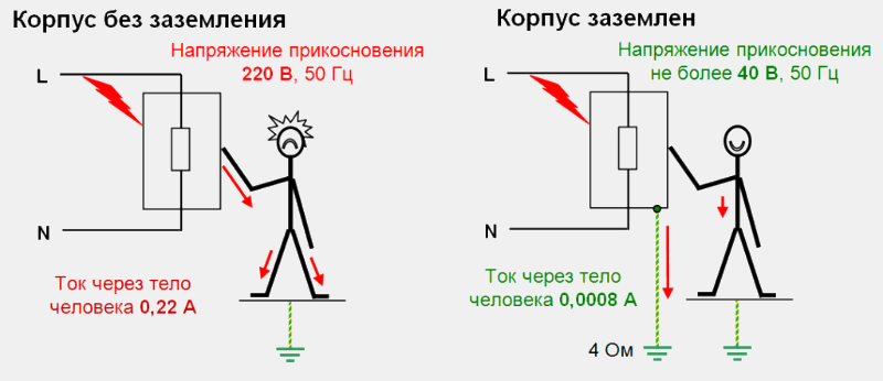
The principle of operation of the grounding system
Important! The magnitude of the current component flowing through the human body largely depends on the isolation of his legs from the ground.
If you wear rubber shoes or a thick protective mat, it decreases in absolute value, ideally approaching zero. With this in mind, professional electricians usually work on equipment while sitting on a rubber mat and wearing rubber boots.
Information for those who still do not know why grounding is needed
Why is grounding needed? It is difficult to find a person who does not know what electricity is. Many people got their first negative experience from contact with it in childhood, sticking their little fingers into a socket. Remember those invigorating sensations? The thing is that the human body consists of 70% liquid, and it is known to conduct current very well. And if you pass a powerful flow of electricity through this body, the tissues will be destroyed.

Serious electric shocks cause disability or even death
It is sometimes surprising how adults get into unpleasant situations with electricity, knowing these basics perfectly well.
Important! If you accidentally find yourself near a downed high-voltage power line, leave the danger zone by jumping on one leg. As soon as you put both feet on the ground, you will inevitably receive an electric shock.
By the way, professional electricians, who have been hit by this same current more than once, use not only insulated tools and special gloves, but also dielectric shoes. It prevents the circuit from closing.
Someone might say: well, I don’t walk under power towers, I’m under my own roof, safe. There is no such need for grounding for a private home. And he will be wrong. Just in the house, the insidious 220 volts are just waiting for you to relax. A simple example: you installed a modern electric boiler and connected it to a battery circuit. Everything was wonderful for the time being, until the heater suddenly failed and a phase got into its body. Well, if an adult decides to touch the batteries, he has a small chance of survival. What if it's a child?
It is in order to avoid such catastrophic consequences that grounding is necessary in the country, in the house, in the apartment, in the office.
Grounding schemes, which one to choose
Before making grounding in your private home, you will need to familiarize yourself with the features of the arrangement and operation of protective systems that involve the use of one of the well-known schemes. To do this, you need to consider the following important points:
- When organizing the power supply of any modern facility, in addition to the neutral and phase buses, a so-called “grounding” conductor must be connected to it.
- Its main purpose is to protect people from dangerous potential that enters the body of devices when the insulation of conductors is broken.
- To do this, the grounding bus on the substation side is connected to a special grounding element (circuit), which is installed directly on its territory.
Additional information: Thanks to this, the protection function via the neutral core (combined with the working zero or via a separate conductor) is transferred to the consumer side.
At the same time, the grounding devices considered here in the house are usually classified as “repeated” chargers, duplicating station ones in case of a break in the neutral (combined PEN conductor).
According to the method of grounding the neutral core of the transformer at the substation and the facility on the consumer side, all used circuits are divided into the following two categories:
- Firstly, these are systems with a solidly grounded neutral, which are the most common method of grounding transformers whose secondary windings are connected by a star. In this case, their midpoint is permanently connected to the circuit.
- Secondly, circuits with the so-called “isolated” neutral are often used, in which the middle point is not connected to ground or is connected to it through the high resistance of the protection device.
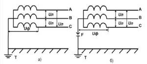
a) a network with a solidly grounded neutral, b) a network with an isolated neutral connected to the ground through an arrester
Useful note: In the second case, the working windings of the transformer perform a separating function and are usually used for industrial purposes or in special electric heating installations.
Their use is associated with the need to isolate current-carrying parts of equipment from the ground loop. According to the rules of electrical installations, a solidly grounded neutral is usually designated as “TN”. One of the most common methods of protective use of such a neutral is to connect metal housings of devices to it via a separate bus.
Types of grounding systems (GS)
When studying the latest edition of the PUE, one immediately notices that Chapter 1.7 of the document provides the following list of protective circuits:
- TN-C or a system with combined working and neutral conductors (English “common” means “common”);
- TN-S or a circuit with separate routing of these buses (“select” or separate wiring);
- TN-CS is a method that is a combination of the 2 previous approaches;
- special schemes for connecting equipment to protective circuits with an isolated neutral, designated as TT and IT.
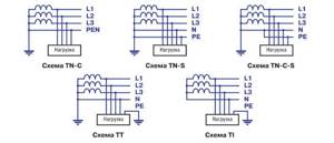
Basic grounding systems for electrical networks
The correct choice of a grounding system that is optimally suited for the specific operating conditions of equipment in a private home is another problem that requires an immediate solution.
Selecting a grounding system
It is recommended to resolve this issue at the design stage of a suburban building, that is, long before the construction of the object itself begins. The parameters of the electrical wiring installed in the building (selection of a set of electrical installation products, in particular) depend on which system of protection against electric shock is chosen. In a situation where a cable with two working conductors runs down to the house from a high-voltage pole, this means that the TN-C type grounding system is used in the supply.
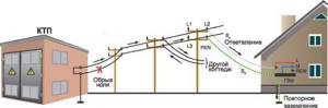
A cable with two working cores runs down to the house from a high-voltage pole
Please note: In this case, re-grounding is mandatory, since the working and grounding conductors are combined (PEN).
Artificially splitting it on the input-distribution panel strip will allow you to isolate a separate PE wire, which can already be used to organize a local grounding loop. This type of protective system is obsolete and is used only in older buildings.
Connecting the house to the ground loop using the TN CS and TN-S system
If a major renovation of a private house is planned with a complete replacement of electrical wiring, the TN-CS system is chosen as a temporary measure. It can be used until local power grid services upgrade them and install a five-core power cable (with a separate grounding bus) to the region. By the way, in this case (according to experts), organizing re-grounding on a personal plot will not hurt at all. When implementing this scheme, a common or combined wire PEN is used on part of the route from the substation to the consumer, and on the supply to the facility equipment it is divided into PE and N.
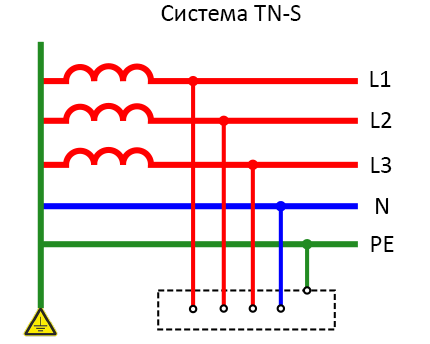
The most expensive in terms of associated costs, but the most convenient and reliable in operation, is the TN-CS circuit. This is a TN-S type system operating in conjunction with transformers with a solidly grounded neutral. In this case, the PE and N conductors are separated along the entire length of the power line from the transformer substation to the consumer. That is, they come to it as two independent buses: a zero working N and a zero protective PE wire. As already noted, to guarantee the security of the facility itself and the people working in it, the PE grounding wire can be connected to a circuit located near a private home. In this case, there are no particularly stringent requirements for the contract itself.
However, if you have this system, you will have to put up with its characteristic disadvantages, which are as follows:
- Electrical wiring throughout the house and outbuildings should be laid with a three-core wire.
- If you have a 3-phase power supply of 380 Volts, you will need a cable with 5 cores.
- In this case, the cost of components and materials increases significantly.
Important! On the other hand, when operating such a system, the safety of working with the equipment being serviced increases and the arrangement of re-grounding is simplified.
Modern power supply lines (both overhead and cable) are laid only using a five-core cable protected by the TN-S system.
TT system
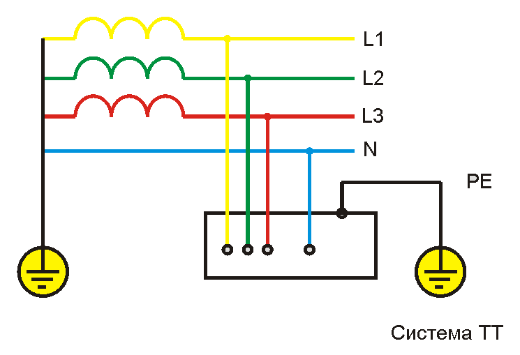
TT grounding system
This system is most popular for grounding private houses, cottages and country houses.
The peculiarity of this method of protecting equipment and people working on it is its use only in situations where no other grounding system is suitable. In this case, the neutral core of the substation transformer does not have direct electrical contact with the grounding busbar, which in turn is connected to a separate grounding loop.
Important! That is, in this system, the neutral network wire (the so-called “neutral”) is not connected to the grounding circuit installed on the consumer side.
Specific situations when the choice of a TT system will be required are described in detail in the current regulations (PUE, paragraph 1.7.59, in particular).
Important! Since the drain current that occurs in an emergency situation may be insufficient to trigger the usual protection, according to paragraph 1.7.59, an RCD or an RCD is additionally installed in it.
Close to TT in design is the IT system, which can be examined in detail in the next section.
Connecting the house to the ground loop using the IT system
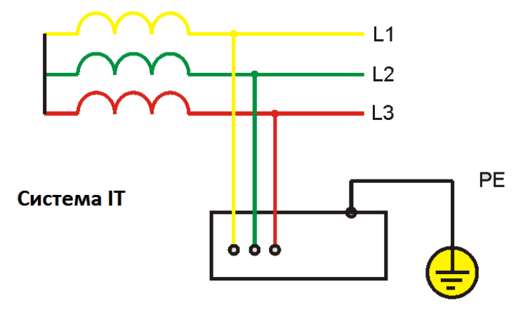
IT system
This method is used if the neutral of the substation transformer is completely isolated from the ground. Alternatively, it can be connected to it through a spark gap, the resistance of which is high at low voltages and decreases sharply when they increase above the limit level.
Additional information: This device reliably protects station electricity consumers from primary voltage entering the secondary part of the winding.
In such a connection circuit, the power network supplying power to electrical installations lacks not only the neutral wire N, but also the grounding bus PE. At the same time, they do not have single-phase voltage in the literal sense of the word. All consumers connected to such a line receive a linear voltage of 380 Volts, operating between phases A, B and C). Due to the fact that the short-circuit currents in this system, like the previous case, are not very large, the use of RCD devices or differential circuit breakers is considered mandatory.
To conclude this section, we note that in nature there are no grounding systems that would be universal and suitable for all occasions. Each of them has known pros and cons, nevertheless fulfilling the main task - creating the safest working conditions for service personnel and ordinary energy consumers. A competent approach to choosing the type of system protection is impossible without a clear understanding of what it is intended for and how it works in power lines.
Types of ground loops
When arranging grounding loops in a house with their own hands, work performers can use the following options for their manufacture:
- Preparation of a triangular structure with sides of equal length, selected depending on the requirements for the ground electrode.
- Assembly of the protection system in the form of a linear (extended) structure arranged around the perimeter of the protected structure.
- The use of the so-called “modular-pin” version.
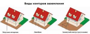
Three types of grounding loop: triangle, linear circuit, modular-pin grounding
Let's consider each of these approaches to making grounding in private property in more detail.
Triangle
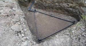
A grounding loop in the form of an equilateral triangle is the most common type of charger, most often installed in private homes. To manufacture it, you will need to prepare the following set of elements that make up the structure:
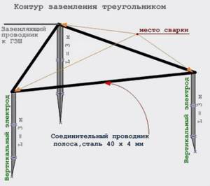
An equilateral triangle ground loop is the most common type of grounding device.
- Three metal pins (rods) at least 2.5 meters long.
- Steel jumpers connecting the rods into a single structure (they are prepared in the same quantity).
- A thick copper or steel busbar required to connect the remote structure to the main grounding contact located in the distribution cabinet.
The plane of the triangular contour formed by steel strips with pins located at the corners should be located in a pre-dug trench approximately 50-60 cm deep.
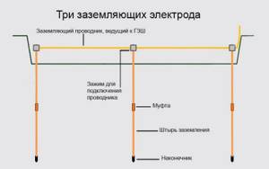
Linear outline
This type of protective structure is installed in situations where several devices or pieces of equipment located at a considerable distance from one another are supposed to be connected to the charger. It is a linear structure consisting of a number of pins driven into the ground, the distances between which are calculated using classical formulas.
Linear diagram of a ground loop for a private house
From the resulting structure, similarly to the previous case, a branch (2) is made towards the distribution panel with the main grounding bus (GZSh). Before calculating such grounding, it should be remembered that the number of steel blanks used is limited by the characteristics of the spreading of emergency current. You can familiarize yourself with the parameters of the linear memory in the corresponding sections of the PUE.
Modular-pin grounding
The modular pin system is an example of a modern approach to solving a technical issue. It includes the following required elements in its kit:
- Metal rods one and a half meters long with threads cut on their working part (the surface of these blanks is covered with a layer of copper on top).
- Threaded couplings made of brass and serving as connecting elements for vertically driven pins.
- Brass clamps are of a special design, ensuring the connection of metal pins with the bridging strip.
- The tips of rods driven vertically into the ground.
- A working attachment with an impact screw tip that provides impulse transmission from a vibrating tool (vibrating hammer).
Modular-pin grounding device for a private house
Please note: For reliable protection against moisture and subsequent corrosion, all connecting threaded elements are treated with anti-corrosion graphite paste included in the delivery set.
It is well preserved during the operation of the structure and does not spread when the elements are strongly heated, providing the required resistance to the spread of emergency current. The anti-corrosion tape included in its composition is highly resistant to aggressive solutions and reliably protects steel grounding elements from destruction. The remaining parts have a standard design and standard dimensions, determined by the assembly technology of the modular-pin design.
For information on how to make modular-pin grounding, read our article “Do-it-yourself modular-pin grounding: instructions, installation.”
How to ground a private house with your own hands
Many people prefer to carry out this work themselves in order to save money, and also to be sure that the grounding of the house is really done with high quality. This process does not take much time or any special skills. It is quite enough to first have a good understanding of the grounding technology, and then carry out everything in a clear sequence, according to our recommendations.
For this you will need special grounding strips and vertical grounding conductors; you can purchase them at any hardware store.
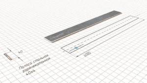
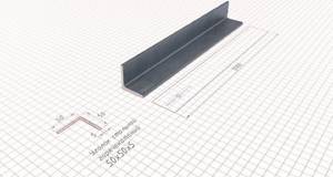
A corner with dimensions of 50x50x5 mm can act as a vertical grounding conductor. The grounding strip may well be strip steel, the width of which is 40 mm and the thickness is 4 mm. These are the main materials with which you can make reliable grounding of a private house with your own hands. Remember that reinforcement is not suitable for such purposes, because it is made of hardened metal, which does not distribute electricity well, transferring it to the ground.
Copper materials are perfect, but such grounding will cost you more. When current passes through steel, its oxidation processes increase several times, so it will quickly become covered with rust. That is why copper materials are preferable, but if there is no such financial opportunity, steel is quite suitable.
You also need to select a cable. To do this, add up the power of all household appliances that are in the house, because it may well be that they will all be turned on at the same time. Choose a cable whose bandwidth is at least a third greater than the resulting number. If you choose a cable with a cross-section that is too small, grounding will not work, the discharge will not go to the ground in time, which can lead to damage to household appliances.
Rules and requirements of the PUE
At any residential property located within the city limits and beyond, in accordance with the requirements of the PUE, special protection against dangerous voltages of 220/380 Volts is organized. For this purpose, special steel structures called grounding devices (GD) are installed on their territory. Their main purpose is to create conditions that guarantee the protection of people living in the house from electric shock.
In accordance with the PUE, chapter 1.7., part 1, clause 1.7.72, the dimensions of metal blanks are selected taking into account the need to obtain the required resistance to the flow of current into the ground. For various structural elements, these indicators may vary from sample to sample. However, their minimum sizes must comply with the following standards:
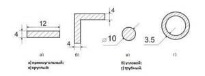
- the connecting strip between the pins cannot have a standard size of less than 12x4 mm (section 48 mm2);
- the pins themselves based on the corners are selected with sides of 4x4 mm;
- when using a round reinforcing bar, the cross-section should not be less than 10 mm2;
- the metal pipe should have a wall thickness of about 3.5 mm.
Please note: Having the owner of the house with data on the operating characteristics of the electrical circuit, in particular, will protect animals and residents from electric shock.
When arranging it, it is necessary to act in accordance with the provisions of industry standards regarding the operation of the equipment available at the site.
Rules and requirements for the ground loop
There are only five basic but mandatory rules. To understand how grounding is done, it is enough to remember and apply them. The list includes the following postulates:
- The minimum radius of removal of the external contour from the building is 1 meter, maximum 10. The optimal distance of the electrodes from the foundation is from 3 to 5 m.
- The pins are buried by 2-2.5 m. 20-30 cm are left visible. This is necessary for attaching the connecting strip. Work can be done in a trench, and then the structure can be covered with soil.
- The bus connecting the external circuit with the electrical panel must have a minimum cross-sectional area of 15 square millimeters.
- The connections are welded when it comes to electrodes and strip. The shield can be provided with a bolt fastening.
- Before installation, check the total resistance of the system, which should not be more than 4 Ohms for 380 V and 8 Ohms for 220 V.
When digging in, you should start from another rule. Before making a contour, check the level of soil freezing. It is different for each region. The pins must be dug to great depth. Otherwise, after freezing they will be squeezed to the surface. And such a system will not be effective enough to operate in harsh winter conditions.
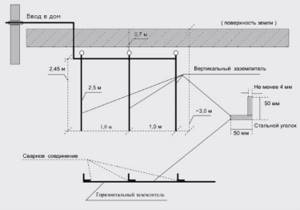
Device and design of the grounding loop
Classic grounding in a private house or simply a grounding conductor contains in its design such mandatory elements as:
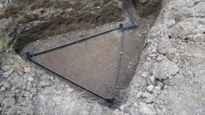
- A set of metal pins or rods driven into the ground to a depth of approximately 2-3 meters (they are placed in a pre-dug trench in the shape of a regular triangle).
- Flat steel jumpers connecting these pins for welding (photo below).
Triangle ground loop
- A special tap made of copper wire or steel strip, necessary to connect the structure to the main grounding bus (it is installed in the distribution cabinet of a private house).
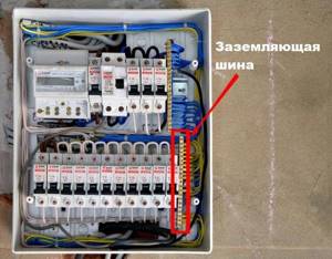
Main grounding bus in the distribution board
The copper grounding conductor goes to the PE bus - the main grounding bus
Additional information: The plane of the triangular contour made of steel strips is usually located at a depth of approximately 50-60 cm.
Having familiarized yourself with the main structural elements of the protective circuit, you can proceed to studying material on how to properly make a grounding circuit in a private house.
External circuit device
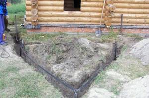
1. Before making grounding in a private house, you need to select a place for the external part of the grounding loop. The most suitable places are those in which there is practically no movement of people, and its location should be as close as possible to the house - optimally 1 m.
It is necessary to exclude the possibility of a person being at the location of the circuit because if the protection is triggered, this can have fatal consequences.
The best places are along the fence on the back side of the house, under blind areas, but the most attractive is under static decorative elements, for example, columns or garden sculptures, or simply fence off the danger zone, cover it with a dome, etc.
Sandy soils pose some problems, to increase the conductivity of which it is recommended to pour a saline solution at the rate of 100 g of salt per 1 liter of water under the base of the ground electrodes, but this method has a significant drawback - accelerated corrosion of the metal, which will ultimately lead to a decrease in the rated power of the circuit.
In cases where such a danger cannot be completely excluded, you should consider constructing an open loop, for example, in the case of regular flooding of the area with melt or flood waters, this option is more correct.

2. Next, you can directly begin to carry out excavation work, namely, to prepare a triangular (or other) shaped trench with sides of 1.2 m (the permissible limit is from 1 to 2 m) and a ditch leading to the house. The depth should average 50-60-70 cm.
3. After this, using a prepared grounding kit for a private house, metal circuit elements - grounding conductors - are driven into the appropriate and pre-designated places using a sledgehammer to a depth of at least 2 m.
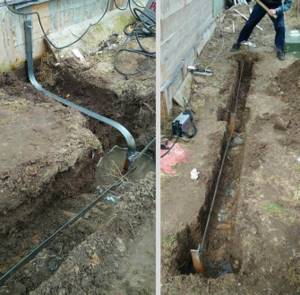
4. After this, using a welding machine, the upper ends are connected with metal strips or a rod. Also, using welding, one of the vertices of the triangle and the end of the metal rod or plates leading to the house are securely tacked. The second end of this element is brought to the house.
Next, using a bolted connection, a cable is connected leading from the house and pulled through a hole in the wall made using a hammer drill with a drill of the appropriate diameter.
5. After completing this stage of work, you can start filling and compacting the trenches. and the external work can be considered completed - the next step is to make connections in the house.
Grounding system calculation
Let's consider the calculation of protective grounding using the example of a linear structure, the pins of which are driven into the ground near the house. When conducting it, you will need to know the following initial indicators:
- Dimensions and total number of steel bars.
- The distance between them (installation pitch).
- Depth of immersion of pins.
- Specific soil resistance in the zone of protection.
According to the proposed method for calculating the grounding loop, its main or general task is to find out the required number of rods and determine the parameters of the steel connecting strip.
Example of memory calculation
As an example, we consider the calculation of the resistance of a single vertical rod (photo on the right). To carry it out
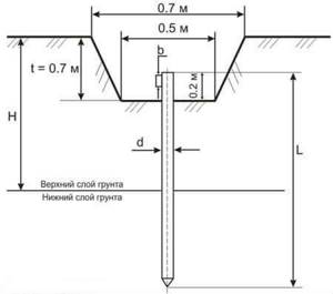
Installation diagram of a single vertical ground electrode
the following data is used:
ρ – soil resistivity (in Ohms per meter);
L – total length of the original rod (in meters);
d – its main standard size (diameter) in meters;
T is the distance from the surface of the earth to the middle of the pin.
If we exclude the influence of factors that determine the spread of current in horizontal elements, the resistance for vertical stakes is calculated as follows:
The required number of rods that guarantees the required conductivity value (without taking into account horizontal components) is determined from the following formula: where Rн is the standard spreading indicator standardized by PTEEP.
Taking into account the previously unconsidered horizontal elements, the formula for determining the number of rods takes on the following form:
where ηв is the load factor of the circuit breaker, taking into account the influence of flow currents of different rods on each other.
Additional information: When two rulers of tinder are placed in parallel, their mutual influence is much stronger.
If their arrangement is excessively “dense,” the complex resistance of the circuit breaker increases noticeably. The conductivity value obtained as a result of the proposed calculations is then rounded up.
The considered calculation method can be fully automated if you use an online calculator for calculating grounding resistance, specially designed for these purposes.
How to install a circuit yourself
To make your own ground loop, you will first need to select its type, and then carry out preparatory work based on this design. They include such mandatory procedures as choosing a location for the grounding circuit, selecting the necessary blanks, pins, jumpers, etc., as well as preparing a pit for the grounding loop.
Please note: As an example of manufacturing, we have chosen the simplest triangular design.
Let us consider the stages of the upcoming work in more detail.
Choosing a place for installation
When choosing a site in the local area suitable for arranging a protective contour, we proceed from the following considerations:
- it should not be located too far from the house; this will not only save on the connecting bus due to its short length, but also reduce the resistance of the current flow circuit;
- the soil at the site where the control panel is installed must be soft enough to allow metal pins to be driven into it;
- The quality of the soil on the site also affects the effectiveness of grounding (loams, plastic clay and peat have minimal resistance).
Important! If suitable soil layers are deep, the length of the corner pins will have to be increased to reach the desired soil layers.
We install the structure
First, a small pit about 40-50 cm deep is prepared, shaped like a triangle with dimensions slightly larger than each side of the future grounding structure. All subsequent actions are carried out in the following order:
- First of all, vertical grounding conductors are driven into the corners.
- Then their ends protruding from the ground, at a distance of approximately 30 cm from the ground surface, are connected to pre-prepared steel jumpers by welding.
- After this, a steel strip with a cross-section of at least 48 square meters is welded to one of the peaks (which is located closer to the house). mm and is brought as close as possible to the distribution panel.
- At the end of the strip, a steel bolt is welded to which a copper conductor with a cross-section of at least 16 square meters is screwed. mm.
- Its other end is inserted into the distribution panel and fixed in it to the main ground bus (GZSh).
Installation of a ground loop in the shape of a triangle
Installation of a linear grounding loop
At the final stage of work, the steel structure, ready for operation, is covered on top with previously discarded earth, which is then compacted well.
You can find detailed instructions for installing a ground loop in the article on our website.